다수 체인과 다중 접촉 성격을 지닌 발 메커니즘에 대한 충격량 흡수 기반 해석
© Korea Robotics Society. All rights reserved.
Abstract
Foot mechanisms play the role of interface between the main body of robotic systems and the ground. Biomimetic design of the foot mechanism is proposed in the paper. Specifically, multi-chained and multiple contact characteristics of general foot mechanisms are analyzed and their advantages are highlighted in terms of impulse. Using Newton-Euler based closed-form external and internal impulse models, characteristics of multiple contact cases are investigated through landing simulation of an articulated leg model with three kinds of foot. It is shown that in comparison to single chain and less articulated linkage system, multi-chain and articulated linkage system has superior characteristic in terms of impulse absorption as well as stability after collision. The effectiveness of the simulation result is verified through comparison to the simulation result of a commercialized software.
Keywords:
External impact, Internal impact, Multiple contact, Foot mechanism.1. Introduction
Impact due to collision between the environment and the robot system occurs at the contact point during the transition from motion to constrained motion. The interacting force at the contact point is difficult to control, and the modeling and control of impact have been considered as an important issue in the field of robotics.
When human and animal contacts environment, there are many simultaneous contact points. When a bird lands on the ground, two or three toes of the bird experience simultaneous ground contact. When the human grasps an object, fingers more than two collide with an object, simultaneously.
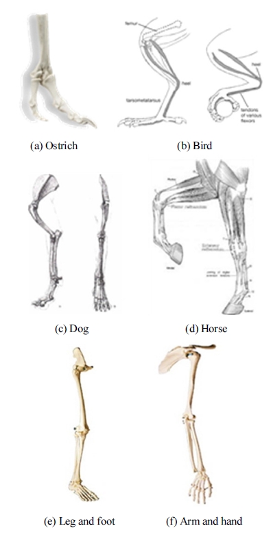
In general contact problem like the above- mentioned cases, multiple ground contacts occur more frequently as compared to the single ground contact. Fig. 1(a) through Fig. 1(d) show that legs and feet of animals consist of large-sized bones and small-sized bones. Specially, the foot of horse only has large-sized phalange instead of small-sized toes. Fig. 1(e) through Fig. 1(f) show the skeleton of arm and leg of human. Similarly to animals, leg and arm of human also consist of largesized bone and small-sized bone in hand and foot. We will show in this paper that those articulated nature of proximal bones plays an important role to minimize or absorb impact due to collision to the environment.
Recently developed locomotion mechanisms with feet can be classified as a bi-pedal robot and a quadruped robot. The well-known ASIMO[1] developed by Honda Co. Locomotion is the first successful humanoid robot. WABIAN-2 from Waseda University of Japan has a toe degree of freedom unlike ASIMO. This robot’s walking is similar to the human walking because it has one toe[2]. H7 developed at the University of Tokyo uses various sensor information in order to get a balance of robot[3]. Humans and animals have several toes. However, previous humanoid models have limitation in adaption to various environments because most of foot mechanisms are rectangular shaped. They can walk just on an even terrain. Though such foot mechanisms have a soft material like rubber[3] or spring[4] in order to absorb an impact from ground contact, they cannot structurally absorb the impact. Chung and Yi[5] analyzed toe mechanisms of humans and animals. They claimed that multi-legged and multi-jointed foot structure were shown to be an intelligent mobility playing the role of impulse absorption and that prior to control action by actuators, passive adaptation to unknown environment is crucial. Seo and Yi[6] analyzed the human foot structure and proposed a biomimetic foot mechanism and its closed-from dynamic model, which consists of a toe, an ankle, a heel, and springs replacing the foot muscles and tendons. It was shown through simulation that using five toes and springs, this foot could adapt to various environments in a stable manner. However, impulse model and its analysis for such multi-chained leg mechanism have not been addressed yet.
In this work, we propose a Newton-Euler based closed form internal impulse model for multi-chained robotic systems in case of multiple contacts. The structure of the multi-chained and articulated foot models is introduced in section 2. Its dynamic model and general impulse model are introduced in section 3. External impulse model is reviewed in section 4. Section 5 introduces a closed form internal impulses model for multiple contact cases. The effectiveness of the foot mechanisms is shown in section 6 through simulation and its effectiveness is verified by comparison with the simulation result of commercially available software.
2. Structure of Foots
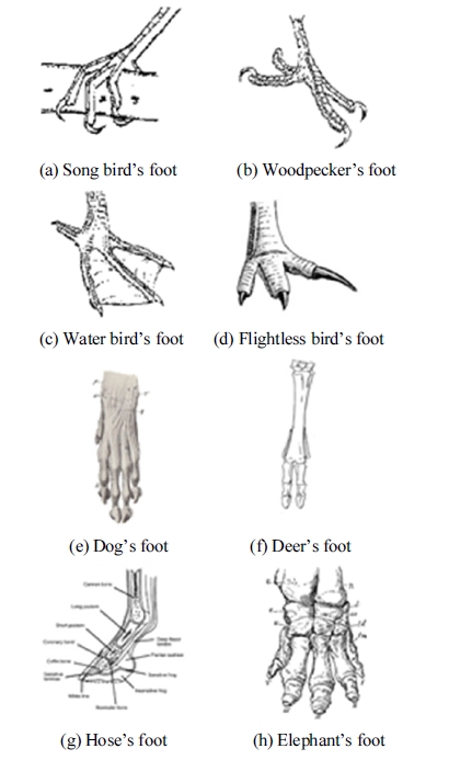
Birds have many different shapes of feet as shown in Fig. 2(a) through Fig. 2(d). Song birds or perching birds (warblers, thrushes, wrens, etc.) have independent, flexible toes, with one pointing backwards, ideal for grasping perches. When perching birds sit, a tendon on the backside of the ankle automatically flexes locking their toes around the branch. With feet locked, sleeping birds do not fall. Woodpeckers have two toes pointing forwards and two backwards for climbing up, down, and sideways on tree trunks. Water birds such as duck have webbing between their toes for swimming. Gulls also have feet similar to these so they do not sink while walking in the sort sand or mud near the water’s edge. Strong-legged flightless birds, like the cassowary, protect themselves by kicking with their powerful feet and sharp claws. These feet help for running, landing, and take-off[7].
Also, most mammals have various shapes to their feet as shown in Fig. 2(e) through Fig. 2(h). Canids (wolves, dog and foxes) have a complex foot structure and have four digits on each foot. The inside toe on the front foot, called the dewclaw, is much smaller and has become vestigial, which implies that it no longer has much, if any, function. On the hind foot, the first toe has been lost completely. Ungulates (deer, hippo, and pig) have even fewer toes. Artiodactyls (even-toed ungulates) have a cloven or two-part hoof in which the third and fourth digits bear the weight. In deer, the first toe has been completely lost and the second and fifth are greatly reduced. Horses are perissodactyla (odd-toed), having a non-cloven hoof. They bear the weight on the third digit [8]. The only evidence of an elephants five toes buried within the flesh of the foot are the toe nails. Actually, the toenails are cornfield shields in the skin and are not attached to the fingers/digits. Interestingly, not all of the toes have nails either. Overall, it is generally accepted that the African elephant has four toenails on the front feet and three on the back as opposed to the Asian elephants which have five on the front and four on the back. Its feet play a role in creating holes in which water can collect, for digging up roots from the ground, and for navigating difficult terrain[9].
Based on the analysis of the foot structures of birds and mammals, common characteristics of such foot systems is as follows :
- (i) foots are multi-chained system
- (ii) each chain is articulated (many joints and links)
In the following sections, we discuss the dynamic model and impulse model of such multi-chained foot mechanisms.
3. Dynamic Model of a Floating Mechanism
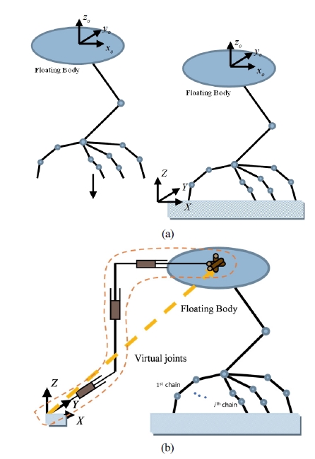
In this section, we derive the dynamic model of robotic systems with a floating body. Consider a multi-chained robotic system of Fig. 3(a).
This robot is initially floating in the air and comes to contact the ground at multiple points. The kinematic model of this robot can be depicted as Fig. 3(b), which includes virtual coordinates representing the floating behavior.
The dynamic model of the ith open chain with single contact point is given as[11]M1
| (1) |
where if denotes the Lagrangian coordinates of the ith open-chain. T and FI denote the joint torque vector and external force vector, respectively. and denote the inertia matrix and inertia power array of the ith chain, respectively. G denotes the Jacobian relating the joint torque vector to the external force vector.
The dynamic model of the whole robot system with multiple contacts can be expressed as
| (2) |
The Lagrangian coordinates consists of the virtual joint vector () and motor-controlled joint vector ().
When a robot system interacts with environment at multiple points, (2) can be rewritten as the following partitioned form[10]
| (3) |
where is a null vector because the virtual joints are not activated, and denotes the joint torque vector at the motor-controlled joints. So, (3) can be decomposed into two components; one for the virtual joints and another for the active joints.
By eliminating the acceleration vector () of the virtual joint, the dynamic model in terms of the motor-controlled joint set can be expressed as [4]
| (4) |
where
and
and N denote the impulsive external force at the ith contact point and the number of the contact point, respectively. The relationship between the velocity of ith contact point and the motor-controlled joint velocity can be expressed asM5
| (5) |
where denotes the Jacobian, relating the ith contact point’s velocity to the motor-controlled joint velocities.
4. External Impulse Model for Multiple Contact
Most generally, the impact is partially elastic in the range of 0 < e < 1 . When the coefficient of restitution ( e ) is known, the relative velocity of the colliding bodies immediately after impact can be obtained. The component of the increment of the relative velocity along a vector that is normal to the contact surface given by
| (6) |
where v1 and v2 are the absolute velocities of the colliding bodies immediately before impact, and Δv1 and Δv2 are the velocity increments immediately after impact.
Integration of the dynamic model given in Eq. (4) over contacting time interval givesM7
| (7) |
Since the position and velocities are assumed finite all the time during impact, the integral term involving become zero as Δt goes to zero, as does the term involving actuation input . Thus, we obtain the following simple expressionM8
| (8) |
where is defined as the external impulse at the ith contact point. Thus, the velocity increment of the joint variables for N contact points is
| (9) |
The velocity increment at the ith contact point is obtained by the following kinematic relationship.
| (10) |
Assume that the robot impacts on a fixed solid surface, then the absolute velocity and the velocity increment of the fixed surface are always zero (v2 = Δv2 = 0). Substituting (10) into (6) and congregating them from i=1 to i=N, we haveM11
| (11) |
where .
When the friction on the contacting surface is negligible, the impulse always acts at the ith contact point along the normal vector . Thus, we have
| (12) |
Finally, the external impulse at the ith contact point is obtained by extracting the ith row component of (12) as follows
| (13) |
where .
From (13), we derive the magnitude of the impulse along the normal vector at the ith contact point as follows
| (14) |
which is a general external impulse model for multiple contacts. Featherstone[10] presented an initial framework for multiple contacts distributed over multiple links based on projection matrices. The result given by (14) is based on Newton-Euler approach. Chung and Yi[13] introduced external and internal impulse models in case of multiple collisions, which will be used in the analysis of multi-chain foot mechanisms.
5. Internal Impulses Model for Multiple Contact
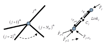
When a robotic system collides with the environment, the joints of the system experience internal impulses along constrained directions of joints. The magnitude of the internal impulse cannot be measured unless we attach sensors at the contacting surface of joints. Consider a serial chain with Nbr branches shown in Fig. 4. The internal impulse model for such multiple contact case is introduced in this section. Using the internal impulse model, we can analyze the internal force transmitted to links and momentum change of the system.
The relationships between the velocity increments and the impulses in the jth coordinate frame attached to the jth link are obtained as
| (15) |
| (16) |
by integrating the Newton-Euler equation with respect to time. In (15) and (16), mj and are the mass and the moment of inertia of the jth link, respectively. The velocity of the jth mass center and the angular velocity of jth link are denoted as and , respectively. is the rotation matrix transforming the (j+br)th coordinate frame to the jth coordinate frame.
The increments of the velocity of the jth mass center and the angular velocity of the jth link are obtained by
| (17) |
| (18) |
where and denote the Jacobians relating the velocity of the mass center and the angular velocity of the jth link to the joint velocity vector, respectively.
Substituting (17), (18), and (9) into the left-hand sides of (15) and (16) yieldsM20
| (19) |
| (20) |
If the kth link experiences the external impulse at the Nk contact points, then (15) and (16) are modified asM21
| (21) |
| (22) |
(19) through (22) can be expressed as an augmented form as followsM23
| (23) |
where the matrix given byM24
| (24) |
is identical to the case of a single contact. The submatrices of are defined as follows:
However, the block matrices [D] and [B]with Nk contact points in the kth link are formed as followsM25
| (25) |
andM26
| (26) |
where
and .
Therefore, the closed form internal impulse model at the joints of the multi-chained manipulator with multiple contact points are formulated as
| (27) |
As noted in (27), the internal impulse at joints is directly affected by the external impulse () and also function of robot geometry.
6. Simulation
6.1. Impulse analysis for the foot models
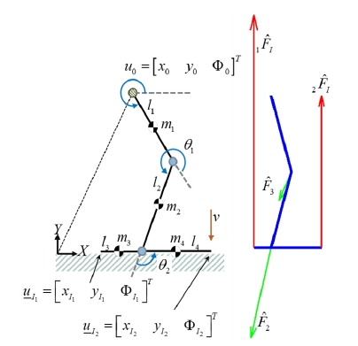
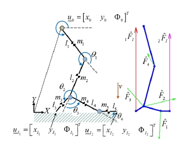
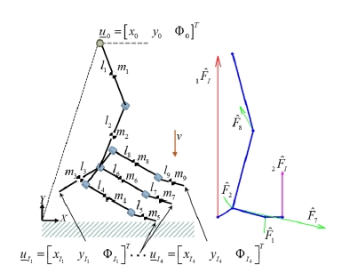
We assume that a leg and foot model is initially in the air and will land on the ground with a constant speed of 3.43 m/s. We assume that each sole of the foot collides to the ground at a point at the instant of colliding. The foot model of Fig. 5 has a flat sole, which collides to the ground at two points at the instant of collision. The soles of the foot models in Fig. 6 and Fig. 7 consist of two and four chains with articulated joints, respectively. Table 1, Table 4, and Table 7 show the kinematic and dynamic parameters for the floating body. It is assumed that the coefficient of restitution e is 0.8 and the friction constant on the ground is zero.
The three different sole models are compared in terms of external and internal impulses experienced at the contact points and the internal joints, respectively. It is shown from the simulation data of case1 (Table 2 and Table 3) and case 2 (Table 5 and Table 6) that the external and internal impulses of the multi-chained and articulated foot is considerably small as compared to the foot with a flat sole. This is because the multi-chained and articulated linkage is able to absorb the impulse as the form of momentum by the movement of all joints and links. As the location of joints is far from the ground, the amount of internal impulses gets decreased as shown in the simulation data.T4T7
As the second observation, the external impulses ex perienced at the right ends of the foot get decreased as the number of toes gets increased as noted in Table 5 and Table 8. However, the total sum of the external impulse experienced at the tips of the two different foots of Fig. 5 and Fig. 6 are identical. They are evenly distributed to several chains. The only difference is that as the number of soles increases, the amount of internal impulse gets decreased as shown on Table 6 and Table 9. Thus, merit of having many toes is that the external impulses are distributed through the articulated links of the sole. As a result, in aspect of design or reliability, this is good since the internal impulse experienced at each joint gets smaller and thus the foot is able to sustain its mechanical structure even for very high impact force.
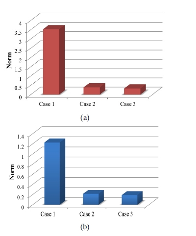
Fig. 8 shows graphs for comparison of external and internal impulses norm, respectively. Here, the norm of external impulse is defined as (i is number of contact point) and the norm of internal impulse is defined as (i is number of joints). It is shown in the graphs that the impulse norms of multi-chained foot with articulated joints are 6 to 10 times smaller than those of the flat foot. This is due to absorption of the impulse as the form of momentum in such multi-chained and articulated foot mechanisms shown in Fig. 6 and Fig. 7. Thus, multi-chained and multiple contact geometry greatly enhances the impact performance with respect to the amount of impulses experienced at impact.
6.2. Impulse analysis using commercially available software
In order to verify the simulation result of this paper, which is based on multi-body dynamics and our impulse model, we compare the result of the proposed models with that of commercially available software. We employ multi-body dynamics software called ‘DAFUL’ made of Virtual Motion Co.[12]. However, such multi-body simulation software just returns the values of impact force at the ground, not the amount of impulse. Thus, by integrating the impact force profile with respect to time, the external impulse at the contact point can be calculated. Furthermore, DAFUL does not provide the amount of internal impulse, either. This is the limitation of commercial software. Thus, the analytic impulse model proposed in this work is valuable to analyze multi-chain and multiple contact problems.
Fig. 9 and Fig. 10 show the simulation result for the flat foot based on DAFUL. In comparison to the external impulse obtained in Fig. 5 and Fig. 7, the external impulse (Fig. 9(c) and Fig. 10(c)) calculated by integrating the impulsive force (Fig. 9(b) and Fig. 10(b)) provided by the DAFUL software with respect to time is almost identical. This indicates the exactness of the proposed, analytic impulse model. Tables 10 and 11 summarize comparison of the external impulses of the foot model with three toes. Not only receiving less impulse, the multichained and multiple contact foot mechanism provides landing stability[13] even in uneven terrains.
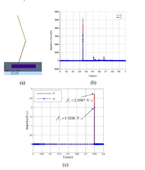
Analysis of external impulses for flat foot model : (a) Foot model of flat type at two contact points, (b) Impulsive force calculated at DAFUL, (c) External impulse based on the impulsive force of (b)
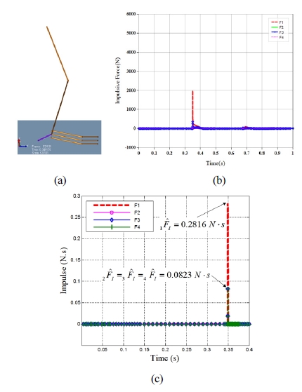
Analysis of external impulses for foot model with three toes : (a) Foot model of multi-chained type with four three toes, (b) Impulsive force calculated at DAFUL, (c) External impulse based on the impulsive force of (b)
7. Conclusion
The contribution of this work is suggestion of a closed form external and internal impulse model of the multichained robotic systems for the multiple contact case. This impulse model is not equipped in commercially available software. Thus, additional numerical procedure is necessary to compute such properties.
In this paper, using the impulse models, we show the effectiveness of the proposed impulse model by comparing four different soles of a biomimetic foot. The lessons obtained from this work are summarized as follow;
- (1) More articulated links receive less external and internal impulses.
- (2) More multi-chained structures receive less external and internal impulses at the foot. Thus, reliability of the mechanical structure of the foot is enhanced.
- (3) Stability after landing is also improved as the number of toes gets increased[6].
As ongoing work, a biomimetic approach that takes into account muscle structure is undertaking as a future research topic[14,15].
References
- Sakagami, Y, Watanabe, R, Aoyama, C, Matsunaga, S, Higaki, N, Fujimura, K, The intelligent ASIMO: system overview and integration, in Proc. IEEE/RSJ Int. Conf. Intell. Robots and Systems, (2003), p2478-2483.
- Takahashi, Y, Nishiwaki, K, Kagami, S, Mizoguchi, H, Inoue, H, High-speed pressure sensor grid for humanoid robot foot, in Proc. IEEE/RSJ Int. Conf. Intell. Robots and Systems, (2005), p1097-1102.
- Li, J, Huang, Q, Zhang, W, Yu, Z, Li, K, Flexible foot design for a humanoid robot, in. Proc. IEEE Int. Conf. Automation and Logistics, (2008), p1414-1419.
-
Yang, H, Shuai, M, Qiu, Z, Wei, H, Zheng, Q, A novel design of flexible foot system for humanoid robot, in Proc. IEEE Conf. Robotics, Automation and Mechatronics, (2008), p824-828.
[https://doi.org/10.1109/ramech.2008.4690883]

- Chung, J.H, Yi, BJ, Intelligent mobility playing the role of impulse absorption, in Proc. Int. Conf. Distributed Autonomous Robotic Systems, (2008), p109-119.
- Seo, JT, Yi, BJ, Modeling and analysis of a biomimetic foot mechanism, in Proc. IEEE/RSJ Int. Conf. Intell. Robots and Systems, (2009), p1472-1477.
- Fernbank Science Center, Bird Feet, [Online], http://www.fernbank.edu/Birding/bird_feet.htm, Accessed: April 15, 2017.
- Arizona Game and Fish Department, Wild Signs, [Online] http://www.azgfd.gov/i_e/ee/resources/wild_kids/signs712.pdf, Accessed: April 15, 2017.
- The Feet - Elehost Web Design, [Online], http://elephant.elehost. com/ About_Elephants/Anatomy/The_Feet/the_feet.html, Accessed: April 15, 2017.
-
Featherstone, R, Rigid body dynamics algorithms, Springer, (2008).
[https://doi.org/10.1007/978-1-4899-7560-7]

- So, B.R, Yi, BJ, Landing motion analysis of human body motion considering impact and ZMP condition, in Proc. IEEE/RSJ Int. Conf. on Intelligent Robots and Systems, (2004), p1972-1976.
- Virtual Motion, [Online], http://www.virtualmotion.co.kr/, Accessed: April 15, 2017.
-
Chung, J.H, Yi, BJ, Modeling of external and internal impulses in case of multiple collisions, Int. J. Modern Physics B, (2008), 22(9-11), p1455-1460.
[https://doi.org/10.1142/s021797920804692x]

-
Imran, A, Yi, BJ, Impulse modeling and analysis of dual arm hammering task: Human-like manipulator, in Proc. IEEE/RSJ Int. Conf. on Intelligent Robots and Systems, (2016), p362-367.
[https://doi.org/10.1109/iros.2016.7759080]

-
Imran, A, Yi, BJ, Impulse modeling and new impulse measure for human-like closed-chain manipulator, IEEE Robot. Autom. Lett, (2016), 1(2), p868-875.
[https://doi.org/10.1109/lra.2016.2525730]

2006 영동대학교 전자공학과(공학사)
2008 한양대대학 메카트로닉스공학과(석사)
2009~현재 한양대학교 메카트로닉스공학과 (박사과정)
관심분야: biomimetic design of robot, medical robot
1999 한국기술교육대학교 제어기계공학과 (공학사)
2008 한양대학교 전자전기제어계측공학과 (석사)
2010~현재 한양대학교 지능형로봇학과(박 사과정)
관심분야: mechanism design, medical robot

